No. 7.3.1
Soldering Surface Mount Chip Components, Point To Point
Method
OUTLINE
This procedure covers the general guidelines for soldering surface mount chip
components. The following surface mount chip components are covered by this
procedure. While all of these components are different, the techniques for
soldering are relatively similar
Chip Resistors
The component body of chip resistors is made out of alumna; an extremely hard,
white colored material. The resistive material is normally located on the top.
Chip resistors are usually mounted with the resistive element facing upwards to
help dissipate heat.
Ceramic Capacitors
These components are constructed from several layers of ceramic with internal
metallized layers. Because metal heats up much faster than ceramic, ceramic
capacitors need to be heated slowly to avoid internal separations between the
ceramic and the metal layers. Internal damage will not generally be visible,
since any cracks will be inside the ceramic body of the component.
NOTE
Avoid rapid heating of ceramic chip capacitors during soldering operations.
Plastic Body
Another style of chip component has a molded plastic body that protects the
internal circuitry. There are a number of different types of components that
share this type of exterior package. The termination styles for plastic chip
component packages vary considerably.
MELF
MELF - Metal Electrode Face cylindrical components. These may be capacitors,
resistors, and diodes. It can be hard to tell them apart - since there is no
universal coloring or component designators printed on the component
bodies.
TOOLS & MATERIALS
Cleaner
Flux
Microscope
Solder
Soldering Iron with Tips
Wipes
PROCEDURE
- Add liquid flux to one pad.
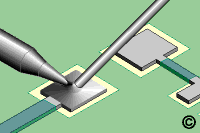
- Prefill one pad with solder. (See Figure 1).
- Clean the area.
- Add liquid flux to both pads.
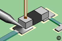
- Place the component in position and hold it steady with a wooden stick or
tweezers so that the soldering iron won't push the component out of alignment.
- Place the soldering iron tip at the junction between the prefilled pad and
component lead. Flow the solder until the component drops down and is soldered
in position. Apply additional solder as needed. (See Figure 2).
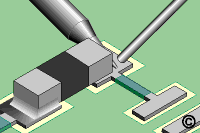
- Remove the tip. Wait a moment for the solder to solidify before soldering
the other side of the component. (See Figure 3).
- Clean, if required and inspect.
|
|
|
Solutions Across the Board
TM
|
|
|
|

Preview our New IPC
Soldering and Rework Skills
Certifications Kits.
Product Class: R/F/W/C
Skill Level: Intermediate
Conformance Level: High
Revision: D
Revision Date: Jul 7, 2000
Repair Service Charge

Surface Mount Chip Component

Figure 1: Prefill one pad with solder.

Figure 2: Place the soldering iron tip at the junction between the prefilled pad
and component lead.

Figure 3: Solder the other opposite side of the component.

Chip Capacitors generally have solid color bodies.
There are five metalized surfaces per end. (face, top, bottom, left, and right
sides)

A - Stripe
B - Beveled Surface
The striped or beveled end is the "positive" (+) or "anode
end".
|
|
|


