No. 8.2.3
Component Removal, Surface Mount Chip Components, Hot
Gas/Air Method
OUTLINE
This procedure covers the most commonly used methods for removing surface mount
Chip components.
NOTE
The goal when removing any component is to remove the component as quickly as
possible
| REFERENCES |
| 1.0 |
Foreword |
| 2.1 |
Handling Electronic Assemblies |
| 2.2 |
Cleaning |
| 2.5 |
Baking and Preheating |
| 7.1.1 |
Soldering Basics |
| 7.1.2 |
Preparation for Soldering and Component Removal |
TOOLS & MATERIALS
Caliper
Cleaner
Cleaning Wipes
Flux, Liquid
Hot Air Removal Tool with Tips
Microscope
Oven
Positioning Table
Rework Stand
Vacuum Pen
PREPARATION
This method uses hot air nozzles that do not touch the component. Gas or air is heated
and forced through a specially designed nozzle and directed onto the component leads and
surface pads.
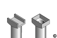
Hot gas/air nozzles come in several sizes to accommodate many of the different styles and sizes of components. Measure the overall length and width of the component to select the proper size nozzle tip. Check the nozzle for proper fit prior to processing the part. Some hot gas/air nozzle designs will heat only the component terminations and pad area. (See Figure 1, Left Side) Some hot air nozzle designs heat the component, the terminations, and pad area. (See Figure 1, Right Side)
NOTE
To prevent the hot gas/air from reflowing the solder joints of adjacent leads/components, use Kapton tape to mask, or create an "air dam", to redirect the air flow away from those solder joints.
Hot gas/air nozzles may or may not include vacuum assistance to lift the component off the circuit board surface.
PROCEDURE
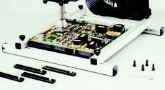
- Place the pre-heated circuit board on the Positioning Table. A heated
positioning table is available to pre-heat the circuit board, or can be used to
maintain the pre-heated temperature when many components need to be removed
from one circuit board. (See Figure 2)
- If desired apply a small amount of liguid flux to the terminations of the
Chip Component and pads.
- Adjust the pressure and temperature output of the hot air tool. (With
the temperature set at 700°F the proper air pressure will cause a Kim Wipe to
turn to a light brown color with the nozzle tip at approximately 1/4"
away from the Kim Wipe.
- Position the hot air nozzle directly over the top of the component and
activate the air flow. Single nozzle pencil type tools will require
movement from termination-to-termination to heat each joint evenly. When
the solder has melted actuate the vacuum assist, or lift off the
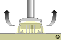
component with a tweezer. Lift the component straight up. (See
Figure 5)
It's difficult to precisely know how long to apply heat prior to safely removing the part. This
is further complicated by the fact that when removing a bank of components,
parts subsequent to the first come off much faster. Obviously, the
smaller the part the quicker it reflows. Small SMT components may reflow
in a few seconds and large SMT components may take more than a minute.
NOTE
Some Chip Components may be glued
to the circuit surface, and require additional effort to remove the part.
Usually if the part is glued to the surface the glue will be visible oozing
from under the part. (To verify, check for evidence of glue on similar
components.) Use caution to prevent damage to the circuit board.
- Clean the area.
|
|
|
Solutions Across the Board
TM
|
|
|
|

Preview our New IPC
Soldering and Rework Skills
Certifications Kits.
Product Class: R/F/W/C
Skill Level: Advanced
Conformance Level: High
Revision: D
Revision Date: Jul 7, 2000
Repair Service Charge

Surface Mount Gull Wing Component

Figure 1: Nozzle at left heats the leads and pads. Nozzle at right heats
component, leads and pads

Figure 2: Rework stand holds hot air rework tool steady and positioning table
keeps circuit board level

Figure 3: After solder has melted lift component straight up
|
|
|


