No. 2.4.3
Coating Replacement, Solder Mask, BGA Locations
OUTLINE
This method is used to replace solder mask or coatings on circuit boards at BGA locations. BGA
locations provide unique challenges due to their inaccessibility after reflow, exposure to high
temperatures, and requirement that the BGA pads only are surrounded by mask. Vias and circuits
that are exposed may cause shorting or BGA solder joint starvation.
TOOLS & MATERIALS
Brush
Cleaner
Color Agents
Epoxy
Foam Swabs
Heat Lamp
Microscope
Oven
Wipes
PROCEDURE
- Clean the area.
CAUTION
Surfaces to be coated must be thoroughly cleaned prior to coating to ensure
adequate adhesion, minimized corrosion, and optimized electrical properties.
- Remove all excess solder from BGA pad and the via (top and bottom side) using solder braid
or desoldering tools. BGA pads should be flat and the vias clear of solder.
NOTE
Vias with solder trapped inside may "volcano" underneath the reflowed component. It is
important to remove the solder if possible.
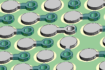
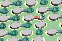
- Scrape solder off the "Dog Bone" section between the BGA pad and connecting via. (See Figure 1)
NOTE
This is to prevent solder from flowing down the "Dog Bone" path to the via location.
- Mix the epoxy or replacement coating.
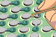
- Apply the replacement coating to the board surface as required.(See Figure
2) Apply a thin coating of epoxy to prevent interference with component placement. Adding
a color agent to the epoxy is not recommended since it may slightly reduce the epoxy
strength or adhesion.
- Cure the epoxy per Procedure 2.7 Epoxy Mixing and Handling. Provide a full cure time to ensure
maximum epoxy strength.
CAUTION
Some components may be sensitive to high temperature.
EVALUATION
- Visual examination for texture, color match, adhesion and coverage.
- Electrical tests to conductors around the repaired area as applicable.
|
|
|
Solutions Across the Board
TM
|
|
|
|
Product Class: R/F/W/C
Skill Level: Intermediate
Conformance Level: High
Revision: A
Revision Date: May 9, 2001
Repair Service Charge

Soldermask Required at BGA Site

Figure 1: Scrape down to the copper surface to create a barrier to solder flow between pad and via.

Figure 2: Apply the replacement coating. A wood stick or small dispenser may be used.

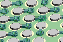
Figure 3: "Dog Bone" area coated with soldermask.
|
|
|


