No. 8.5.3
Component Replacement, Surface Mount BGA Components, Hot
Gas/Air Method
OUTLINE
This procedure covers the most commonly used methods for replacing Plastic
Ball Grid Array (PBGA) components and Ceramic Ball Grid Array (CBGA) components. These packages are typically referred to as Plastic Ball Grid Array
(PBGA) or Tape Ball Grid Array (TBGA) or Chip Scale Package (CSP) components.
CAUTION - Operator Safety
A thorough review of the equipment manual and comprehensive training are
mandatory. Daily maintenance is essential. Consult the equipment manual for more
information.
CAUTION - Component Sensitivity
This method may subject the component to extreme temperatures. Evaluate the
component's tolerance to heat prior to using this method.
CAUTION - Circuit Board Sensitivity
PC Boards are made from a great variety of materials. When subjected to the high
temperatures they are susceptible to the following types of damage:
1. Layer delamination.
2. Copper delamination, separation of pads, barrels of inner layers.
3. Burns and solder mask chipping.
4. Warp.
Each circuit board must be treated individually and scrutinized carefully for its
reaction to heat. If a series of circuit boards are to be reworked, the first several
should be handled with extreme care until a reliable procedure is established.
TOOLS & MATERIALS
BGA specific nozzle
Cleaner
Cleaning Wipes
Flux, Liquid
Hot Air rework Station
Hand held Digital Thermometer
Tape, Kapton
Microscope
Oven
Soldering Iron
Solder
Thermocouples
Vacuum Pen
GENERAL NOTES
- Profiles for both removal and replacement of the selected component must be
developed prior to rework. (See section 8.5.2 for instruction)
- Check the board for any heat sensitive components that may be damaged by the
process, especially near the location of rework.
- Profiles are board and site specific. Profiles that are successful on one
board type are not necessarily effective on other assemblies.
PROCEDURE
REMOVAL
- Select the appropriate nozzle and install into the rework station.
- The nozzle should hold the component securely yet allow for expansion during
the process. Custom nozzles may need to be fabricated.
NOTE
Nozzle to part fit is multidimensional. Closely observe the component ball
location relative to the nozzle bottom. Whether the balls protrude or are deeply
recessed into the nozzle may affect part positioning during reflow.
NOTE
Pre bake the board to drive out accumulated
moisture. The length of pre bake will be affected by the board’s environmental
exposure. A pre bake temperature of 75 °C to 100 °C is recommended.
- Place a pre baked board onto the fixture.
- Attach a monitoring and trigger
thermocouples.
- Establish a bottom side, under part
threshold temperature from which to begin the reflow ramp. 140°C underneath the part should correspond
to approximately 90°C at 2" from the nozzle on the board’s top side.
Choosing a starting point in this approximate temperature range will help to
reduce localized warping during BGA ball reflow.
NOTE
Anti static fixture material may be used when coplanarity
problems exist as the circuit board expands above its glass transition temperature (Tg).
- Apply a small amount of liquid flux to all leads of the component.. A
syringe may be used to inject flux under the device.
- Align the device and nozzle.
- Activate the desoldering profile and monitor the board temperature using the
hand held digital thermometer or other appropriate monitoring device.
NOTE
If the bottom temperature exceeds 200°C, terminate the removal process and
check the process parameters.
- Lift the nozzle when reflow temperatures are reached. A vacuum pen may be
used to remove the part if a vacuum tip is not incorporated into the nozzle
itself.
- Clean the area. Remove all flux residue from the site.
SURFACE PREPARATION
NOTE
This procedure
uses eutectic solder alloy bumps to
prepare BGA pads for combination with BGA part balls. For use of solder paste
see section 8.5.4. Component Rework, High Temperature Balled BGA Components.
- Remove all excess solder from the site (See section 7.1.2 Preparation for
Soldering)
- Clean the area.
- Inspect all pads for damage. It is critical that solder mask is not
disturbed between the pad and its via. Solder volume problems may exist if
solder is allowed to escape down the vias.
- Apply liquid flux to the pads.
- Apply new eutectic solder in consistent
bumps to each BGA pad. The bump angle, surface to pad, should be between 30°
and 45°.
REPLACEMENT
- Select the appropriate nozzle and install into the rework station.
- The nozzle should hold the component securely yet allow for expansion during
the process.
NOTE
Pre bake the board to drive out accumulated
moisture. The length of pre bake will be affected by the board’s environmental
exposure. A pre bake temperature of 75 °C to 100 °C is recommended.
NOTE
To remove moisture from components, it is recommended that all parts are baked
per the component manufactures suggestion. Generally, a 24 hour bake at 125°C
will remove most moisture. This will prevent pop-corning or delamination of the
component.
- Place a pre baked board into the fixture.
- Attach monitoring and trigger thermocouples
- Establish a bottom side, under part
threshold temperature from which to begin the reflow ramp. 140°C
underneath the part should correspond
to approximately 90°C at 2" from the nozzle on the board’s top side.
Choosing a starting point in this approximate temperature range will help to
reduce localized warping at BGA ball reflow temperature.
- Align the device and nozzle.
NOTE
If the bottom temperature exceeds 210°C, terminate the replacement and check
the process parameters.
- Lift the nozzle when well below reflow temperatures.
- Ion fans may be used to cool the components and the board.
- Clean the area . Remove all flux residue from the site.
EVALUATION
- Visual examination of the perimeter spheres for joint shape, alignment and
condition.
- Visual examination for part planarity and condition.
- X-ray examination as required for shorting or joint deformities.
See (Figure 2).
- Electrical tests as applicable
- On removed part, visual evaluation of post reflow condition.
|
|
|
Solutions Across the Board
TM
|
|
|
|

Preview our New IPC
Soldering and Rework Skills
Certifications Kits.
Product Class: R/F/W/C
Skill Level: Advanced
Conformance Level: High
Revision: E
Revision Date: July 7, 2000
Repair Service Charge
Plastic Ball Grid Array Component
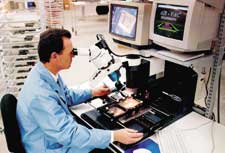
Figure 1: Commercially available BGA Rework Station
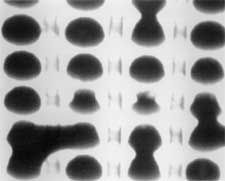
Figure 2: X-ray inspection verifies shorted spheres.
|
|
|

