No. 8.1.1
Component Removal, Through Hole Components, Vacuum Method
OUTLINE
This procedure covers the general guidelines for through hole component
removal using a powered vacuum desoldering tool.
There is basically only one style of through hole component. Whether there
are a few leads or many, or whether the component is large or small, the
component removal principles are the same.
TOOLS & MATERIALS
Cleaner
Flux
Microscope
Solder
Solder Removal Tool, Vacuum Type with Tips
Soldering Iron with Tips
Wipes
PROCEDURE - Standard Method
- Inspect the size of the solder joints on the component to be removed. If the
size of the solder joint fillets are minimal, it may be desirable to add
additional solder to form an "excess solder" joint. This will improve
the thermal linkage.
- Apply a small amount of liquid flux to the solder joints of the component to
be removed.
- Align the desolder tip with a component lead end and lightly make contact
with the solder joint. Keep the desolder tip off the pad by allowing it to slide
around on a film of solder.
CAUTION
Do not apply pressure with the solder extractor tip to the lands or other
conductive patterns.
- After the solder has melted, start a rotating or oscillating motion with the
desolder tip. Continue the rotating motion until a change in the
"feel" of the rotating motion occurs. At this instant the solder in
the solder joint is completely molten. Immediately activate the vacuum,
extracting the solder from the solder joint. (See Figure 1).
- Maintain rotation of the desolder tip while continuous vacuum is being
applied. This allows air to cool both the component lead and the plated-through
hole preventing the component lead from resweating to the side of the hole.
- After the solder has been extracted from the solder joint, remove the
desolder tip from the component lead while maintaining continuous vacuum.
- Maintain continuous vacuum for a few seconds to clear the desolder tip.
- Turn off the vacuum.
- Desolder each of the remaining component leads individually using a skipping
method to reduce thermal buildup at adjacent hole locations.
- Probe each component lead to be sure that they are not soldered to the side
of the plated hole and then remove component.
NOTE
If each lead is not completely free, resolder the joint and repeat steps 2 - 10.
- Clean the area.
PROCEDURE - Auxiliary Heat Method
Auxiliary heating may be required on solder joints with a large thermal mass.
This is most common on multilayer circuit boards.
- Inspect the size of the solder joints on the component to be removed. If the
size of the solder joint fillets are minimal, it may be desirable to add
additional solder to form an "excess solder" joint. This will improve
the thermal linkage.
- Apply a small amount of liquid flux to the solder joints of the component to
be removed.
- Place a soldering iron tip against the lead of the component side of the circuit
board. (See Figure 2)
- Align the desolder tip with a component lead end and lightly make contact
with the solder joint. Keep the desolder tip off the pad by allowing it to slide
around on a film of solder.
CAUTION
Do not apply pressure with the solder extractor tip to the lands or other
conductive patterns.
- After the solder has melted, start a rotating or oscillating motion with the
desolder tip. Continue the rotating motion until a change in the
"feel" of the rotating motion occurs. At this instant the solder in
the solder joint is completely molten. Immediately activate the vacuum,
extracting the solder from the solder joint.
- Maintain rotation of the desolder tip while continuous vacuum is being
applied. This allows air to cool both the component lead and the plated-through
hole preventing the component lead from resoldering to the side of the hole.
- After the solder has been extracted from the solder joint, remove the
desolder tip and the soldering iron tip from the component lead while
maintaining continuous vacuum on the desoldering tip.
- Maintain continuous vacuum for a few seconds to clear the desolder tip.
- Turn off the vacuum.
- Desolder each of the remaining component leads individually using a skipping
method to reduce thermal buildup at adjacent hole locations.
- Probe each component lead to be sure that they are not soldered to the side
of the plated hole and then remove component.
NOTE
If each lead is not completely free, resolder the joint and repeat steps 2 - 11.
- Clean the area.
EVALUATION
- In-process QA Inspection should be conducted to ensure component was removed
without evidence of damage to circuit board assembly or plated through hole.
|
|
|
Solutions Across the Board
TM
|
|
|
|

Preview our New IPC
Soldering and Rework Skills
Certifications Kits.
Product Class: R/F/W/C
Skill Level: Intermediate
Conformance Level: High
Revision: D
Revision Date: Jul 7, 2000
Repair Service Charge
Through Hole Component
Figure 1: When the solder melts, activate the vacuum to remove the solder while
oscillating the tip
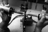
Figure 2: Place a soldering iron tip against the component lead and the
desoldering tip over the lead end.
|
|
|

