No. 5.1
Plated Hole Repair, No Inner Layer Connection
OUTLINE
This procedure covers the repair of a damaged hole that has no inner layer
connection. An eyelet is used to repair the damage to the hole and the eyelet
flanges replace the lands on the circuit board surface.
CAUTION
This procedure is used only to restore the integrity of a through connection in
a double sided board or a multilayer board where there is no inner layer
connection. If there is an inner layer connection see appropriate procedure.
| ACCEPTABILITY REFERENCES |
| IPC-A-600 |
2.0 |
Externally Observable Characteristics |
| IPC-A-600 |
3.0 |
Internally Observable Characteristics |
| |
| PROCEDURE REFERENCE |
| CTC 7721 |
1.0 |
Foreword |
| CTC 7721 |
2.1 |
Handling Electronic Assemblies |
| CTC 7721 |
2.2 |
Cleaning |
| IPC 7721 |
5.1 |
Plated Hole Repair, No Inner Layer Connection |
TOOLS & MATERIALS
Ball Mills
Caliper Gauges
Cleaner
Eyelet Press
Eyelets, Various Sizes
Flux, Liquid
Knife
Micro-Drill System
Microscope
Pin Gauges
Plated Hole Repair Kit
Setting Form Tool, Various Sizes
Setting Anvil, Various Sizes
Solder Iron
Solder
Wipes
EYELET SELECTION CRITERIA
ID - Inside Diameter
The eyelet inside diameter should be a .075 - .500 mm (.003"-.020")
greater than the component lead diameter.
LUF - Length Under Flange
The length of the eyelet barrel under the flange should be .630 - .890 mm
(.025" - 035") greater than the thickness of the circuit board. This added
length allows for proper protrusion when setting the eyelet.
FD - Flange Diameter
The eyelet flange diameter should be small enough to prevent interference with
adjacent lands or circuits.
OD - Outside Diameter
The clearance hole drilled through the circuit board should allow the eyelet to be
inserted without force but should not exceed .125 mm (.005") greater than
the eyelet outside diameter.
NOTE
Be sure to select an eyelet meeting the proper criteria. An eyelet with an
oversize flange may interfere with adjacent circuits. An eyelet that is too
short will not protrude through the circuit board for proper setting.
PROCEDURE
- Clean the area.
- Select an eyelet using the Eyelet Selection Criteria. Use a pin gauge and
caliper to measure the existing plated hole dimensions.
- Insert the appropriate ball mill into the Micro-Drill System. Drill out the
hole removing all the plating. The drilled hole should be .025 - .125 mm
(.001" - .005") larger than the eyelet O.D. (See Figure 1).
CAUTION
This procedure may isolate internal connections on multilayer circuit boards.
- Clean the area.
- Apply a small amount of liquid flux to the land or circuit on the circuit board
surface, if any, and tin with solder using a soldering iron and solder. Clean
the area.
- Insert the eyelet into the hole. If a new circuit is required, the new
circuit may extend into the drilled hole and the flange of the eyelet will
secure the new circuit in place. (See Figure 2).
- Select the proper setting tools and insert them into an eyelet press system.
(See Figure 3).
- Turn the circuit board over and rest the eyelet flange on the lower setting tool.
- Apply firm even pressure to form the eyelet barrel.
NOTE
Inspect the eyelet flange for evidence of damage. Refer to IPC-A-610
Acceptability of Electronic Assemblies.
- Apply a small amount of liquid flux and solder the eyelet flanges to the
lands on the circuit board surface if necessary. Clean the area. Inspect for good
solder flow and wetting around the eyelet flanges and lands.
EVALUATION
- Visual examination, dimensional requirement of land diameter and inside
diameter.
- Electrical continuity measurement.
|
|
|
Solutions Across the Board
TM
|
|
|
|
Product Class: R/F/W
Skill Level: Intermediate
Conformance Level: High
Revision: E
Revision Date: Mar 28, 2001
Repair Service Charge
Damaged Plated Hole
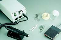
Figure 1: Drill out the hole using a Micro-Drill System and ball mill.
Figure 2: The eyelet flange can be used to secure a new circuit in place.
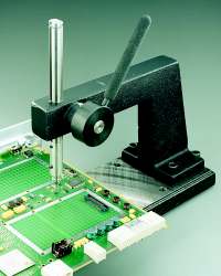
Figure 3: Set the eyelet using an Eyelet
Press.
Figure 4: Completed repair.
|
Tricks of the Trade
A reliable repair\rework method but becoming more difficult due
to smaller holes and lands. Some small eyelet sizes are not available.
|
|
|

