No. 4.2.1
Conductor Repair, Foil Jumper, Epoxy Method
OUTLINE
This method is used on circuit boards to replace damaged or missing circuits on
the circuit board surface.
CAUTION
The circuit widths, spacing and current carrying capacity must not be reduced
below allowable tolerances.
TOOLS & MATERIALS
Buffer
Circuit Tracks
Cleaner
Color Agent
Epoxy
Flux, Liquid
Knife
Micro-Drill System
Microscope
Scraper
Solder
Soldering Iron with Tips
Tape, Kapton
Wipes
PROCEDURE
- Clean the area.
- Remove the damaged section of circuit using a knife. The damaged circuit
should be trimmed back to a point where the circuit still has a good bond to the
PC board surface.
NOTE
Heat can be applied to the damaged circuit using a soldering iron to allow the
circuit to be removed more easily.
- Use a knife and scrape off any solder mask or coating from the ends of the
remaining circuit. (See Figure 1).
- Remove all loose material. Clean the area.
NOTE
It is essential that the board surface be smooth and flat. If the base material
is damaged see appropriate procedure.
- Apply a small amount of liquid flux to the ends of the remaining circuit.
Tin the exposed end of each circuit using solder and a soldering iron.
- Clean the area
- Select a Circuit Track to match the width and thickness of the circuit to be
replaced. (See Table 1) Cut a length approximately as needed. The Circuit Track
should overlap the existing circuit a minimum of 2 times the circuit width.
Table 1 - Common Circuit Track Sizes
| Part No. |
Thickness |
Width |
| 115-2504 |
.002" |
.004" |
| 115-5206 |
.002" |
.006" |
| 115-5208 |
.002" |
.008" |
| 115-5210 |
.002" |
.010" |
| 115-5312 |
.003" |
.120" |
| 115-5315 |
.003" |
.015" |
| 115-5520 |
.005" |
.020" |
| 115-5530 |
.005" |
.030" |
NOTE
The new circuit may be trimmed from copper sheet.
- Gently abrade the top and bottom surface of the Circuit Track with a buffer
to remove the protective coating.
NOTE
A thin protective coating is applied to the Circuit Track to prevent oxidation.
- Clean the Circuit Track.
- If needed, the ends of the Circuit Track may be tinned with solder prior to lap
soldering it in place.
- If the Circuit Track is long or has bends, one end may be soldered prior to
forming the new shape. Place the Circuit Track in position. The Circuit Track
should overlap the existing circuit a minimum of 2 times the circuit width. The
Circuit Track may be held in place with Kapton tape. (See Figure 2).
- Apply a small amount of liquid flux to the overlap joint.
- Lap solder the Circuit Track to the circuit on the circuit board surface using solder
and a soldering iron. Make sure the Circuit Track is properly aligned.
NOTE
If the configuration permits, the overlap solder joint connection should be a
minimum of 3.00 mm (0.125") from the related termination. This gap will
minimize the possibility of simultaneous reflow during soldering operations.
Refer to 7.1 Soldering Basics.
- Bend the Circuit Track as needed to match the shape of the missing
circuit. (See Figure 3).
NOTE
Two wood sticks can be used to make sharp bends in the replacement Circuit
Track. Use one stick to hold the Circuit Track at the bend location and use the
other wood stick to form the shape as needed.
- Wide circuits that cannot be easily formed may be folded over to
produce a sharp bend. (See Figure 4).
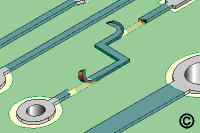
- Form the final shape of the jumper and hold in place with Kapton tape. Lap solder the
Circuit Track to the remaining circuit on the circuit board surface using solder and
a soldering iron. Make sure the Circuit Track is properly aligned. Remove the
Kapton tape used to hold the foil jumped. Clean the area. (See Figure 5).
- Mix the Epoxy. If desired, add color agent to the mixed epoxy to match the circuit
board color.
- Coat the top and sides of the Circuit Track with epoxy. The epoxy bonds the
Circuit Track to the circuit board surface and insulates it. A wooden stick sharpened
at one end may be used to apply and spread the epoxy. (See Figure 6).
- Cure the epoxy per Procedure 2.7 Epoxy Mixing and Handling.
CAUTION
Some components may be sensitive to high temperature.
- Apply surface coating to match prior coating as required.
EVALUATION
- Visual examination for alignment and overlap of foil jumper.
- Visual examination of epoxy coating for texture and color match.
- Electrical tests as applicable.
| |
|
Solutions Across the Board
TM
|
|
|
|
Product Class: R/F/C
Skill Level: Advanced
Conformance Level: Meduim
Revision: E
Revision Date: Jul 7, 2000
Repair Service Charge
Damaged Conductor
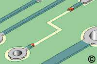
Figure 1: Scrape off any solder mask or coating from the ends of the remaining
circuits.
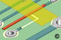
Figure 2: Place the new Circuit Track in position and hold in place with Kapton tape.
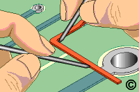
Figure 3: Bend Circuit Track using 2 wood sticks.
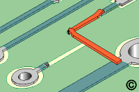
Figure 4: Wide circuits that cannot be easily formed may be folded over to
produce a sharp bend.
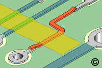
Figure 5: Form the final shape of the Circuit Track then hold in place with Kapton tape
while soldering.
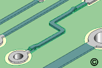
Figure 6: Coat the top and sides of the Circuit Track with epoxy.
|
Tricks of the Trade
This is the most common method we use to repair a damaged or
missing conductor. The flat profile of the pure copper replacement conductors are easy to form and
match the shape and profile of the missing conductor.
|
|
|

