No. 4.3.2
Circuit Cut, Inner Layer Circuits
OUTLINE
This method is used to sever a circuit or short. A small section of the circuit
is removed forming a break. The width of the break should be at least as wide as
the minimum conductor spacing. The Precision Drill System is used with a carbide
end mill. This method is recommended for surface or inner layer circuit cuts.
After milling, the area is sealed with epoxy.
NOTE
This method is recommended for surface or inner layer circuit cuts.
CAUTION
Extreme care must be taken to prevent damage to adjacent or underlying inner
layer circuits. A microscope must be used during milling when extreme accuracy
is required.
| ACCEPTABILITY REFERENCES |
| IPC-A-600 |
2.0 |
Externally Observable Characteristics |
| IPC-A-600 |
3.0 |
Internally Observable Characteristics |
| IPC-A-610 |
10.0 |
Laminate Conditions |
| |
| PROCEDURE REFERENCE |
| CTC 7721 |
1.0 |
Foreword |
| CTC 7721 |
2.1 |
Handling Electronic
Assemblies |
| CTC 7721 |
2.2 |
Cleaning |
| CTC 7721 |
2.7 |
Epoxy Mixing and
Handling |
| IPC 7721 |
4.3.2 |
Conductor Cut, Inner Layer Conductors |
TOOLS & MATERIALS
Cleaner
Color Agent
Continuity Meter
End Mills
Epoxy
Microscope
Oven
Pin Clamps
Precision Drill System
Tape, Kapton
Wipes
PROCEDURE
- Identify the circuit or short to be cut. Determine from the artwork or
drawings where the best location is to make the break. The width of the break
should at least match the minimum required electrical spacing.
- Clean the area.
- If the cut is on an inner layer circuit, mark the coordinates on the circuit
board surface or set up a fixture to precisely locate the board in the Precision
Drill System. (See Figure 1).
- Select the appropriate size end mill or ball mill and insert it into the
chuck of the Precision Drill System. The milling cutter should be slightly
larger in diameter than the circuit to be cut. Set speed to high.
NOTE
End mills are normally single end, two or four flute high grade solid carbide.
- Mill down into the board at the proper coordinates to cut the inner layer
circuits or to break the inner layer short. Do not mill deeper than needed. A
microscope should be used for accuracy. (See Figure 2).
- Blow away material with air and clean the area.
- Check continuity to be sure that the circuit has been cut.
- Mix epoxy. If desired, add color agent to the mixed epoxy to match the circuit
board color.
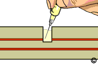
- Fill the milled hole with epoxy up to and flush with the surface. An epoxy
dispenser may be used to accurately control the application of epoxy. Remove any
excess epoxy. (See Figure 3).
CAUTION
Examine milled hole to be sure all material is removed from the hole prior to
filling the hole with epoxy.
NOTE
A slight overfill of epoxy may be desired to allow for shrinkage when epoxy
cures.
- Cure the epoxy per Procedure 2.7 Epoxy Mixing and Handling.
EVALUATION
- Visual examination of cuts for spacing, and unintended damage to surrounding
circuits.
- Electrical tests as applicable.
|
|
|
Solutions Across the Board
TM
|
|
|
|
Product Class: R/F
Skill Level: Advanced
Conformance Level: High
Revision: E
Revision Date: Jul 7, 2000
Repair Service Charge

Circuit Cut, Inner Layer

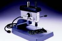
Figure 1: Precision Drill System with base plate to pin circuit board in position
while cutting circuits.

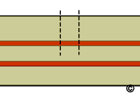
Figure 2: Mill into circuit board at proper coordinates to cut inner layer circuits
as required.

Figure 3: Fill the milled hole with epoxy up to and flush with the surface.

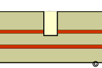
Figure 4: Completed repair.
|
Tricks of the Trade
A routine operation when using a precision
Drill System. This bench top drill
has the depth control needed for accurate inner layer cuts.
|
|
|
