No. 3.4.2
Key and Slot Repair, Transplant Method
OUTLINE
This method is used to modify or repair a key slot, or other cutout in a printed
board or assembly. A replacement piece of matching board material is epoxied
into the area needing repair. A new cut is then machined into the repaired area
if needed.
CAUTION
Care should be taken to limit the application of epoxy to the specific areas
desired and to avoid damage to the conductive patterns, contacts and components.
TOOLS & MATERIALS
Ball Mills
Base Board Repair Kit
Base Material
Cleaner
End Mills
Epoxy
Knife
Micro-Drill System
Milling Machine
Mixing Sticks
Oven
Precision Drill System
Scraper
Tape, Kapton
Wipes
PROCEDURE
- Clean the area to be filled, including the edges.
- Mill out the damaged area using a milling machine or Precision Drill System
and carbide end mill. (See Figure 1).
- Clean the area.
- Install carbide saw into the Micro-Drill System. Set the speed to maximum
and machine a groove in the edge of the circuit board where the new base material
will be installed. The groove must be centered in the edge to ensure that the
new piece will fit properly. The groove width should be approx. 1/3 of the circuit
board thickness. The groove depth should be approx. double the groove width.
(See Figure 2).
- Cut a piece of replacement base board material that is the same thickness
and type as the circuit board. The replacement piece should be longer than the length
of the slot to allow for ease of handling.
- Install an end mill into the milling machine. Machine a tongue onto both
sides of the replacement piece. The dimensions of the tongue should match the
size of the milled groove. (See Figure 3).
- Where required apply Kapton tape to protect exposed parts of circuit board bordering the
prepared area.
- Carefully check the fit of the replacement piece and then clean both the
replacement piece and the slot. The replacement base material should fit firmly
into the slot so that it will not move or fall out when epoxied in place.
- Apply Kapton tape to the surface of the circuit board adjacent to the slot. The Kapton tape
should protect any adjacent contacts or components.
- Mix the epoxy.
- Apply a small amount of epoxy to the edges of the replacement piece and to
the inside edges of the slot.
- Insert the replacement piece into the slot. Check alignment. Remove excess
epoxy. (See Figure 4).
- If needed, apply additional epoxy to the edges of the slot. A mixing stick
sharpened at the end may be used to apply the epoxy.
- Cure the epoxy per Procedure 2.7 Epoxy Mixing and Handling.
CAUTION
Some components may be sensitive to high temperature.
- After the epoxy has cured remove the Kapton tape
- If needed use a knife or scraper and scrape off any excess
epoxy.
NOTE
If needed, apply additional thin coating to seal any scraped areas.
- Cut off excess length of replacement material and file to match contour of
existing edge. (See Figure 5).
- If a new slot is needed, machine using milling machine and appropriate
milling cutter. Use great care to correctly relocate the slot.
- Clean the area.
EVALUATION
- Visual examination and measurement of key slot location and dimension.
|
|
|
Solutions Across the Board
TM
|
|
|
|
Product Class: R/W
Skill Level: Expert
Conformance Level: High
Revision: D
Revision Date: Jul 7, 2000
Repair Service Charge

Damaged Key Slot At Outlined Area

Figure 1: Mill out the damaged area using a milling machine or Precision Drill
System.

Figure 2: Cut a groove into both sides of the key slot using a Micro-Drill System and carbide saw.

Figure 3: Machine a tongue onto both sides of the replacement base material.

Figure 4: Insert the replacement piece into the slot.
|

Figure 5: Cut off excess material and file to match edge.
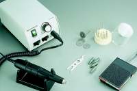
Figure 6: Micro-Drill
System.
|
Tricks of the Trade
This is a challenging rework/repair procedure. Should not to be
attempted by rookies. You may want to send this one out. Give us a call. See Base Board Repair for more info. We recommend
Pre-packaged Epoxy to bond the
replacement material in place. Mix a Color
Agent in with the Epoxy if needed. You'll need a Precision Drill and Micro-Drill if you plan to attempt this one
in-house.
|
|
|

